A hole lot of trouble for loco rebuild fixed
Published: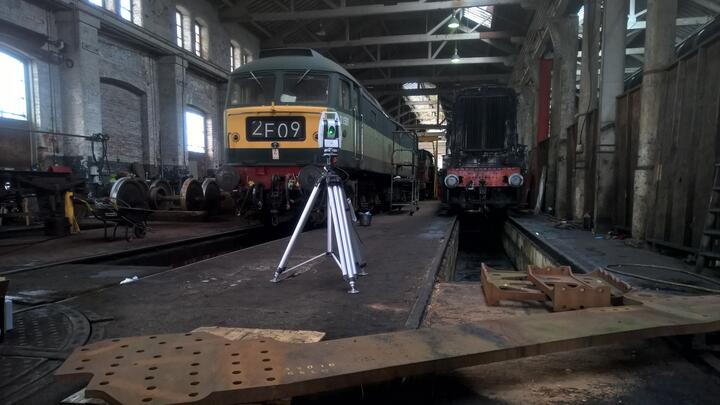
A steam train not seen since the 1960s is being rebuilt by a group of engineering enthusiasts with the help of industrial laser scanning experts at the University of Sheffield AMRC who got the measure of a mysterious discrepancy between the original drawings and the actual locomotive.
The Standard Steam Locomotive Company group has set itself the ambitious challenge to recreate, operate and maintain a lost class of British steam train - a British Railways' Standard Class 6 'Clan' - using the original 1950s design drawings and 21st century engineering; incorporating modern design and manufacturing techniques and technologies into the build.
The University of Sheffield Advanced Manufacturing Research Centre (AMRC) was involved in a major frame alignment measuring exercise for the project after a review of the build inventory showed critical gaps in documentation for some of the key parts relating to the locomotive's frames.
Dr Phil Yates is a chartered engineer at the AMRC working on regional and SME development within Factory 2050, and member of the volunteer group whose headquarters are located at specialist engineering firm CTL Seal Ltd in Sheffield, which has generously allocated an area of its shop floor to give the volunteer team a dedicated space in which to assemble the lost locomotive.
Dr Yates said critical gaps in documentation for some of the parts are thought to be due to the fact that, 80 years ago, there was no direct link between the drawing office and shop floor as the locomotive was designed and constructed in separate locations some 50 miles apart.
"The Standard Class was designed at the drawing office of the Derby Works while the locomotives were constructed at British Railways' Crewe Works between 1951 and 1954. So the drawing office was nowhere near where they made the locomotive and back then people made stuff based on what they knew rather than what was in the drawing. You have to bear in mind the drawing does not show how a part is manufactured.
"In some ways the drawings were a wish of intent. By the time they got to the shop floor - some 50 miles away in Crewe - if there was a mistake, they would correct it and make a note of it in a little black book which more often than not, never made it back to the drawing office for the error to be corrected in the original drawings.
"That’s what these errors are - they show the disconnect between the drawing office and the shop floor. In those days people just had their little black books of how to make stuff. It was all the tacit knowledge on the shop floor that actually made it work. So when people left, how to make these bits just went with them.”
In those days people just had their little black books of how to make stuff. It was all the tacit knowledge on the shop floor that actually made it work. So when people left, how to make these bits just went with them.
Further doubts on the functionality of the parts were raised when the original 1950s British Rail drawings were converted and turned into CAD (computer-aided design) models, as Dr Yates explains.
“One of the main components that caused serious concern were the frame extensions; the CAD had been produced after the part had been previously manufactured prior to the manufacture of the mainframe plates. The way the fastener hole patterns had been datumed on the frame and the frame extensions was not identical, so when the parts were aligned in CAD, the fastener holes did not align. The maximum error on the CAD components was 1.6mm.
“The error was because the two original drawings didn’t match. The person who did the drawing of the frame and the person who did the drawing of the frame extensions - one of them got something wrong or different - so they didn’t align.”
Poor draughtsmanship and not understanding manufacturing methods can lead to misinterpretation of drawings; a problem then as it is in today’s world. Understanding manufacturing methods is essential in dimensioning drawings with clarity.
As both the frames and their extensions had been laser profiled by separate companies to the original drawing, it was assumed that these errors existed in the parts. To ascertain the size of the error, the frames and frame extensions, which were stored in separate locations, had to be measured.
To measure the frame extensions, which were being stored at East Lancashire Railway works, Dr Yates and Factory 2050’s theme lead for inspection and AI, Tom Hodgson, used a Leica Absolute Tracker AT402 laser scanner combined with a Leica B-Probe. The portable coordinate measuring machine, manufactured by AMRC tier one research partner Hexagon Manufacturing Intelligence, enables extreme accuracy over large distances - ideal for the 13ft long frame extensions of a steam locomotive.
When Yates and Hodgson came to measure the 106 holes in the frame extensions they found themselves working in the shadow of the Flying Scotsman, the world’s first high speed train – built in Doncaster – which was in the Bury workshop at the same time.
Dr Yates said: “The frame extensions were over at the East Lancashire Railway works and the Flying Scotsman was there at the time so it was nice to admire the world’s most famous passenger locomotive.
“Tom Hodgson and I did the measurement work on the frame extensions. They were being stored in a freezing cold shed and that was something we had to consider because temperature can affect measurement work.
“Materials can shrink and grow with changes in temperature. To account for that involves some tricky maths and we've compensated for it best we can by gauging how much the material would move by a ten degrees difference in temperature.”
Geoff Turner, the group’s engineering director, said access to University of Sheffield AMRC’s expertise and Hexagon Manufacturing Intelligence’s advanced equipment allowed for fast, accurate data to be collected and for the errors to be remedied quickly.
He said: “The Leica AT402 was ideal for measuring the frame extensions in situ in the engine shed, negating the need to find a dedicated inspection room and giving us accurate data in the three planes identifying the errors which we were able to correct.”
Dr Yates added: “Because we knew this before assembly, we could work out a strategy for re-doing the holes and make slightly oversized fasteners for where the holes were wrong.”
Assembly for the locomotive is being done at specialist Sheffield engineering firm CTL Seal Ltd, which also doubles as the volunteer group’s headquarters after CTL Seal generously allocated part of its shop floor to give the group a dedicated space in which to build the lost locomotive.
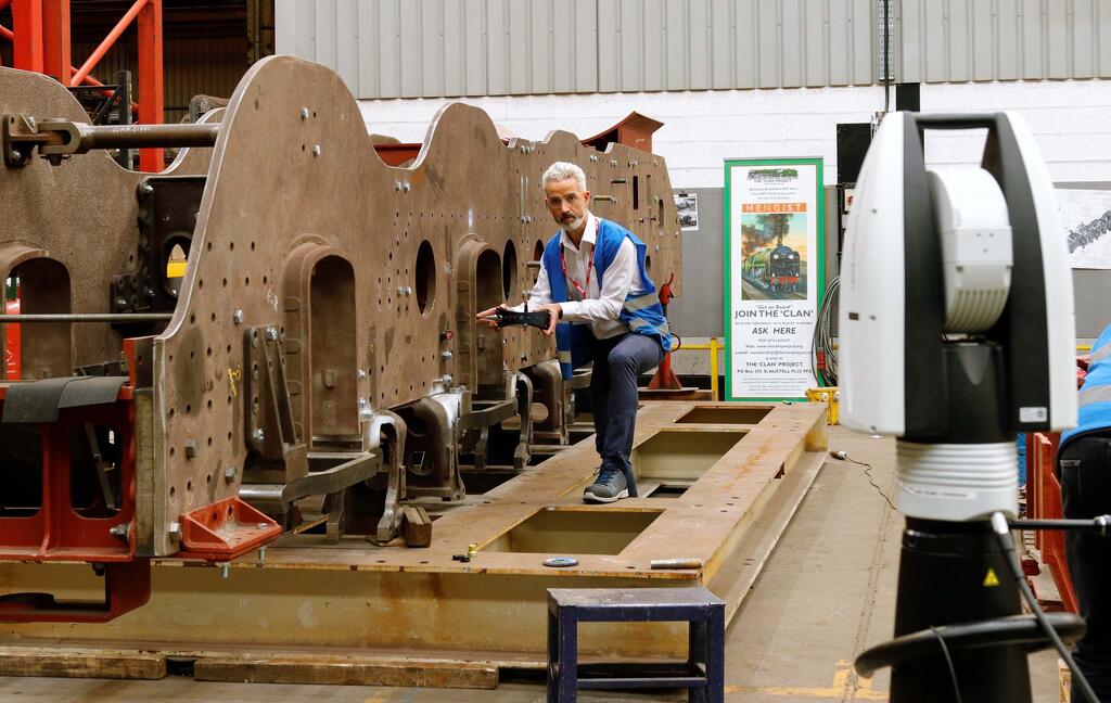
Its frame comprises main frame plates held apart by fabricated steel frame stretchers, cast steel frame stretchers and pressed steel horizontal frame stretchers. All of these components were manufactured by different suppliers so to ensure the different components were all manufactured to the same dimensional accuracy, the project team needed confirmation of the frame assembly dimensions.
The ATS600 has opened doors for us within new sectors where we would not normally be active. Post-Covid-19 this is even more important for us; diversification is the battle cry for many financial planners but this practice is true of what solutions we can offer at Hexagon Manufacturing Intelligence.
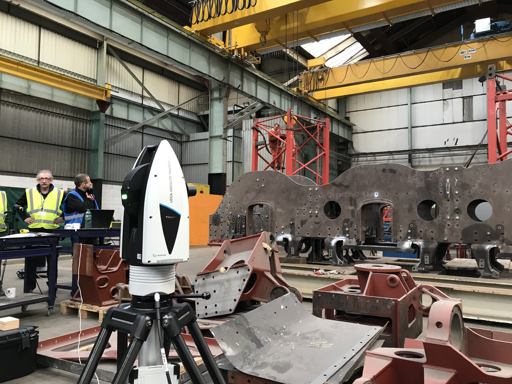
To do this, Yates and the Standard Steam volunteer group enlisted further help from AMRC partner Hexagon Manufacturing Intelligence, this time trialling a new type of targetless scanning tracker - the Leica Laser Tracker ATS600.
Its scanning ability was ideally suited to the task, says Yates, and Hexagon Manufacturing Intelligence loaned one to the project along with the expertise of its application engineers, Tim Gears and Barry Dimelow.
Tim said: “Hexagon has been supporting AMRC through our tier one partnership since 2013. We have been involved in many projects, but not one as interesting as scanning a 1950s steam locomotive.
“I have measured many things, from an Airbus A380 to a Eurofighter, but never a steam locomotive. Seeing first-hand the versatility of our Leica ATS600, and the flexibility that reflectorless scanning gave us made it perfect as the measurement tool of choice.”
The Leica Absolute Tracker ATS600 is a metrology-grade large volume scanner, combining scanning with tactile measurements seamlessly. It has a scanning range from one to 60 metres, and a reflector range of one to 80 metres; a scanning rate up to 1 kHz and a scanning speed of up to ten10 sec/m2. It offers true metrology workflows of integration of large-scale scan data in Spatial Analyzer and Inspire Metrology software. Point cloud data from the ATS600 is also directly available within the application software for immediate feedback, such as build and inspect.
It didn’t fail to impress. Measurements from the first scan, which consisted of 2,788 points, took just two minutes and showed the frame had a significant bow in it. Further investigation revealed the bow had been caused by a packing piece being left in situ, which had been fitted to allow the removal and replacement of one of the frame stretchers for machining.
“The maximum deflection caused by this packing piece was 0.351 inches (8.9 mm),” says Yates. “The scan area was defined by selecting the regions of interest from the frame in CAD and then setting the spacing required. Key features such as the horn guides and datum holes and reference nests were measured by probing with a Spherically Mounted Retroreflector (SMR).”
By using the combined scan and probing data, the rotational relationship of the frames could be determined.
Yates said: “This showed that the frames were rotating around a point between the second and third driving wheel. The point at the exhaust steam spider was 0.119 inches (3.02mm) high. The manufacturing engineers were shown graphically the relationship between the two frames.
“With the frames loosened and then re-aligned, a second scan was completed and that showed that the frames were aligned and they could progress to final bolting. The position and relationship between the horn guides and the cylinder mounting points was also recorded so that in the final machining procedure, a probing and datuming section could be completed thus saving time on the machine.”
Engineering director for the group, Geoff Turner, said the laser scanning survey proved to be another huge help to the project: “It saved so much time compared with using traditional measuring equipment and crucially, it meant that real time adjustments could be made as the survey was in progress.”
Tim added: “The ATS600 has opened doors for us within new sectors where we would not normally be active. Post-Covid-19 this is even more important for us; diversification is the battle cry for many financial planners but this practice is true of what solutions we can offer at Hexagon Manufacturing Intelligence.”